

JOHN BLISS & CO. TAFFRAIL LOGS
Click on the thumbnails below for larger pictures.
|
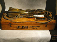 |
This log was "deaccessioned" 6/23/07 and placed aboard the Schooner Virginia for training purposes. This replaced a Negus log which lost its 'fish'. This log only has one fish; spares would be welcome. Contact myself or Schooner Virginia if you have one to donate. |
|
Probably used on inland waterways, such as the Great Lakes, where statute, rather than nautical, miles are used. 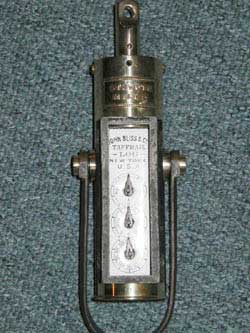 |
 |
The distance a ship travels, as measured by the log, is an essential element of "Dead Reckoning," how a navigator keeps track of the vessel's position. At sea, distances are usually measured in "Nautical Miles". A nautical mile is defined as one minute of latitude. This works out to about 6,076 feet, which is longer than the statute (land) mile of 5,280 feet. Practically, a speed of 10 nautical miles per hour (knots) is equivalent to 11.5 miles per hour on land.
The first logs had a triangular piece of wood attached to a line with knots tied in it. When cast over the stern, the number of knots that ran out in a given time indicated the speed in nautical miles per hour, hence the term "Knots." Casting the log every few hours allowed the navigator to average the speed, and calculate the distance traveled.
Around 1800, the first practical mechanical log was patented. It had a spinner which drove dials through a clockwork mechanism indicating distance, and became known as a patent log. Everything was contained in one unit, which was towed astern on a line, and had to be hauled in every watch to read the register.
John Bliss & Co. made the first mechanical log that separated the spinner and the distance register, allowing the log to be read at any time. However, they did not invent or patent it, as suggested by some authorities. The Taffrail Log, as it's called, was invented by Capt. Truman Hotchkiss, of Stratford CT, and patented by him in 1864. He patented an improved thrust bearing in 1867. I haven't been able to determine when the Bliss Co. acquired the rights and began manufacturing the logs, but some of the company's early catalogs also credit Capt. Hotchkiss with the invention. See the example in Brewington's catalog of Navigating Instruments in the collection of the Peabody Museum, Salem MA. Bliss patents were issued to John and George H. Bliss.
| Number |
Date |
Issued to: |
Description |
|
45,042 |
Nov. 15, 1864 |
Truman Hotchkiss |
Original patent for the Taffrail Log. |
|
63,520 |
Apr. 2, 1867 |
Truman Hotchkiss |
Improved thrust bearing for the log (used in all subsequent Bliss logs) |
|
178,261 |
June 6 1876 |
J & GH Bliss |
Redesign of taffrail register. Now has three dials inline in tubular housing. |
|
208,061 |
Sep. 17, 1878 |
J & GH Bliss |
Improved rotator |
|
296,385 |
Apr. 8, 1884 |
J & GH Bliss |
Improved rotator |
|
Jul. 21, 1885 |
J & GH Bliss |
Reissue of 178,261 of 1876. | |
|
331,369 |
Dec. 1, 1885 |
J & GH Bliss |
Adjustable rotator |
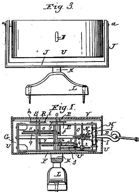
The very first version of this log is pretty much as described by Hotchkiss in his patent. It has a round, rather than tubular, register. I have only seen one example of this log, in the collection of the Peabody Essex Museum in Salem, Massachusetts, and described in M.V. Brewington's book "The Peabody Museum Collection of Navigating Instruments", 1963. It's museum no. M3028, and is shown on plate XLI in the book. The fish shown in the book is a later Bliss fish, but the original, as shown in the patent, is in the box in the museum.
Patent images for the first version of the Bliss Taffrail Log.
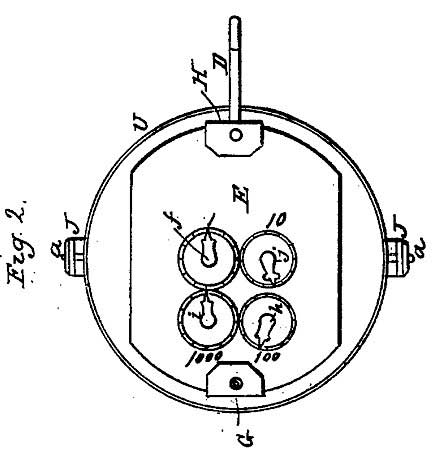
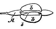
Original design fish or propeller
In 1876, the register and fish were redesigned, and that version is very common, and found with three basic 'signatures' on the dial. The first, illustrated by my first log, lists the first four patents, 1864, 1867, 1876 & 1878. Since patent terms were 17 years, it should have been made between 1878 and 1881.
The second signature shows patent dates of 1876, 1878, and the two 1885 dates, so it must have been made between 1885 and 1893. As stated above, my example of this has been donated to the Schooner Virginia for navigational training.
The third signature was probably made after 1902, as it has no patent dates. I only have the register for my example of this log. This particular example is interesting because it has a brass label showing that it measures the shorter statute, or land, mile, rather than nautical miles normally used in navigation. I have seen several so labeled (with and without patent dates). They were probably used for inland navigation. I have seen a Bliss statute mile log that was used on a Great Lakes vessel.
Several sources indicate that the adjustable spinner (patent 331,369) permitted readings in either nautical or statute miles. This is not true; the gearing in the register determines which mile is measured. The adjustable spinner was designed to correct for variations caused by hull shape and wake pattern.
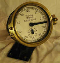
John Bliss & Co. later brought out improved logs, known as the "STAR" and "DOUBLE STAR" followed by the "MARK II" intended for high speed steamships. The older log was then advertised as suitable for "Sailing vessels and Steamers of moderate speed."
The "STAR" had an odometer (digital) readout, and the "DOUBLE STAR" had three dials: a dial reading in tenths of a mile, the main dial reading 0-100 in 1 mi. increments, and a second small dial reading 0-1000 mi. in 100 mile increments. The BLISS MARK II SHIP LOG is the last Bliss taffrail log that I'm aware of, and is similar to the DOUBLE STAR except that it doesn't have the small 0-1000 mi. dial. These all had a wheel governor, and a fish with a weight several feet in front of it. The governor served as a flywheel to smooth out the rotation of the line, and the weight served to keep the "fish" from jumping out of the water at speed. These modifications allowed use of these logs with high speed steamships. My MARK II lacks all but the register (dial unit), and appears to be unused.
|
First. Secure the Log to the taffrail; pass the line through the rotator and make an eye, which draw back within the tube, serving the line with twine or leather to make it fit tightly in the rotator to prevent chafing; put a pine toggle through the two holes and the eye. Second. Use 200 feet of line for all ordinary speed; at 2 or 3 knots, 100 feet will be found preferable. Third. The rotator should not be connected with the line by a chain or heavy wire, the weight of which would cause it to sink deeper and over-register. Fourth. It is better to make a note of the reading and not set the hands, which are securely protected to prevent any person from meddling with them. Fifth. When hauling in the rotator, pay out the loose line overboard and when the rotator is in hand, haul in the line at leisure; care should be taken not to injure the rotator by striking the vessel. Sixth. Oil the spindle once a day, with any oil except kerosene, Lard or Sperm Oils preferable. Occasionally draw out the movement and oil the pivots and worm. Seventh. Make a becket in the eye of the spindle, to hook into, which will prevent wear of the hook and eye. NOTE The rotator spins uniformly, but owing to the motion of the vessel, the twist in the line is delivered at the spindle at slightly irregular intervals. The rotation can be made quite steady by doubling the line for about four feet at the end nearest the register, and spreading the two parts by means of a light stick of wood about ten inches long, thereby diminishing the wear on the spindle, without materially affecting the indications. |
Adjustable Rotator It has been found that a Log, of whatsoever make, which would correctly indicate the distance sailed by one vessel, might be found inaccurate upon another. There seem to be little doubt that these varying results are caused by a difference in the character of the wake, due to the method of propulsion, or the form of the model. To obviate this difficulty, rising from the use of a rotator having blades with one unalterable angle of pitch, we have adopted our Adjustable Log Rotator. To render this rotator adustable, we cut slits in the rear
end of two of the blades, forming tongues, which can be bent
forward or backward to produce the desired correction. 1/4 Thickness of the Brass Blade_______ 2
to 3 per cent A bend in the contrary direction will decrease the speed of
the rotator the same amount. CAUTION.-No bending whatsoever should be done until the error, if any of the rotator has been accurately ascertained by repeated trials, and then, as this mode of correction is exceedingly sensitive, great care must be taken not to bend the tongues further than directed in the above table. |

Text and pictures copyright Norman Bliss 2002
Page created 6/21/02.
Modified 12/13/11